Understanding how information is presented on a wiring harness 2D drawing is the key to accurate interpretation. While different companies may use varying formats, the core principles remain consistent. To help you master wire harness blueprint reading, here are the 7 most important aspects to focus on:
1. Circuit Identification in Wiring Harness Drawings
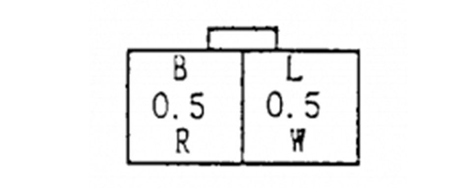
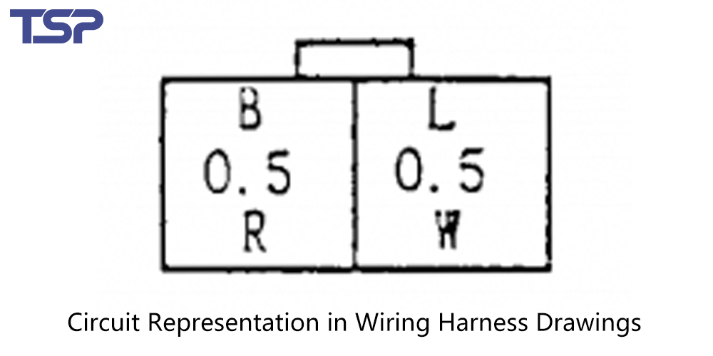
In wiring harness design, “circuit” typically refers to the designated wire name. These are usually defined during the schematic phase.
A common way to express circuit information includes:
Connector Cross-section View (represented as a block)
Circuit Code: e.g., B, L (identifies the circuit)
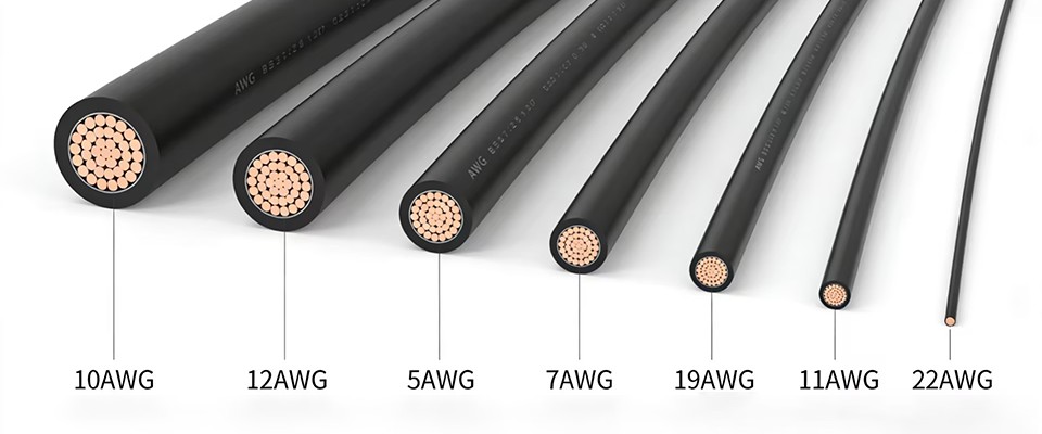
Wire Gauge: e.g., 0.5 (diameter in mm²)
Wire Color Code: e.g., R for Red, W for White
Each wire’s specifications, including size and color, are detailed further in the wire selection guide section of your technical documentation.
2. Connector Details and Specifications
Each connector shown in a 2D harness drawing should include:
Connector brand and part number
Terminal part numbers
Sealing components (such as plugs or grommets)
Proper labeling ensures accurate manufacturing and assembly. Here’s how connectors and branch tying points are typically represented:
(Insert example image or diagram here)
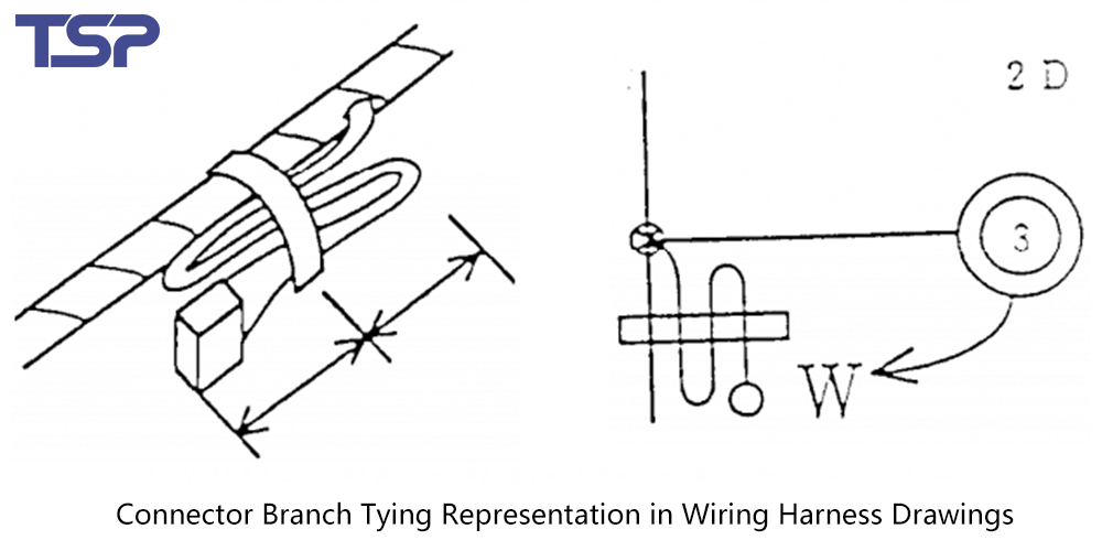
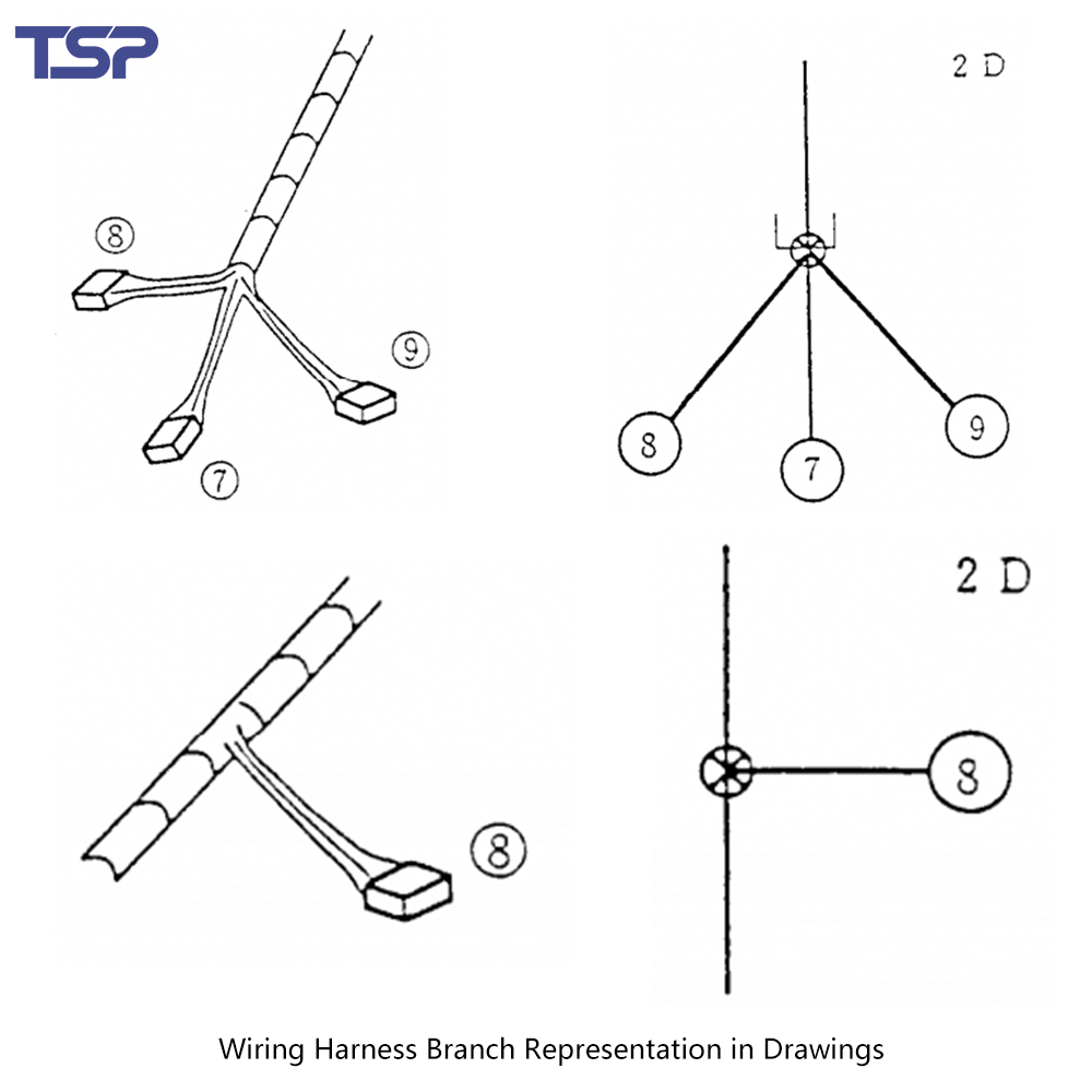
3. Wire Branching and Output Direction
In 2D harness layouts, only the centerline of each wire segment is usually illustrated. However, the layout must clearly show:
Branching directions
Output angles of wires (no need to define angles numerically)
Relative positions of wire branches
This clarity helps ensure proper harness routing during production and installation.
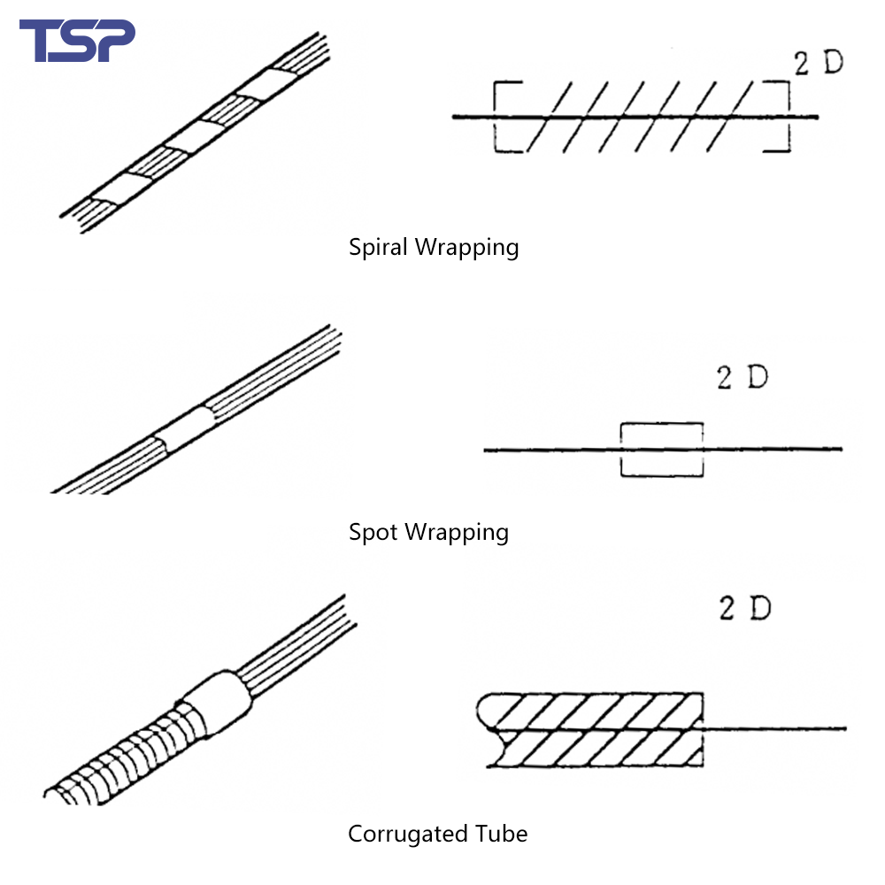
4. Wire Wrapping and Bundling Methods
The method of wire wrapping or taping must be illustrated using standard graphic symbols that are placed around the wire segment centerline.
These symbols represent:
Taping types
Protective tubing
Wrapping directions or areas
(Insert example symbol chart if available)
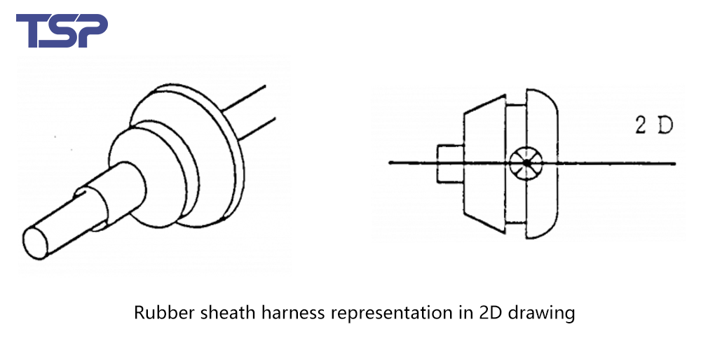
5. Harness Fixtures & Mounting Elements (Including Section Views)
2D drawings also need to express fixing components like:
Flat clamps or fasteners
Rubber grommets or protective sleeves
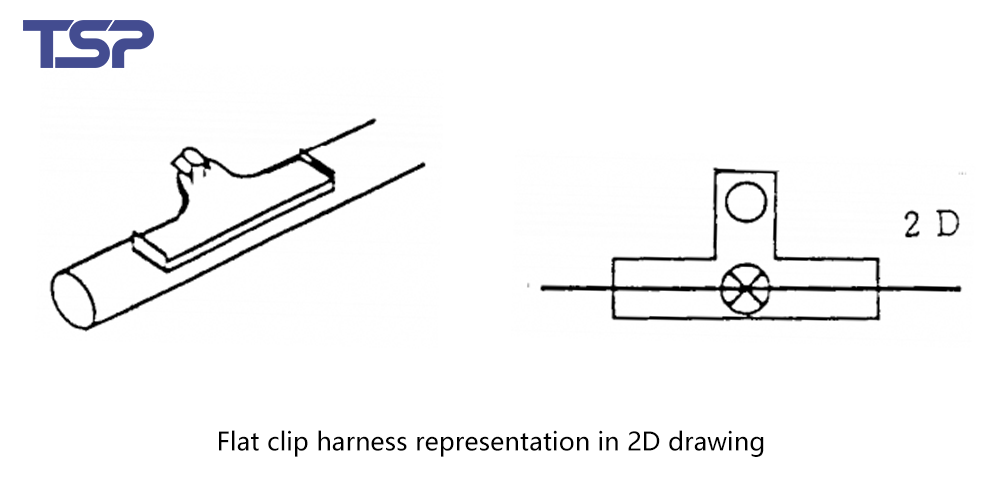
For each fixing element, show:
Top view (plan) representation
Reference point for positioning (usually the center)
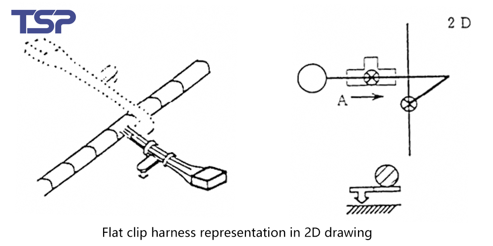
If the component cannot be clearly shown in top view, include:
View direction arrows
Cross-sectional views
This ensures clarity when manufacturing and assembling complex routing.
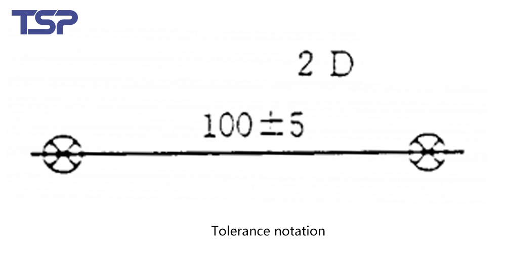
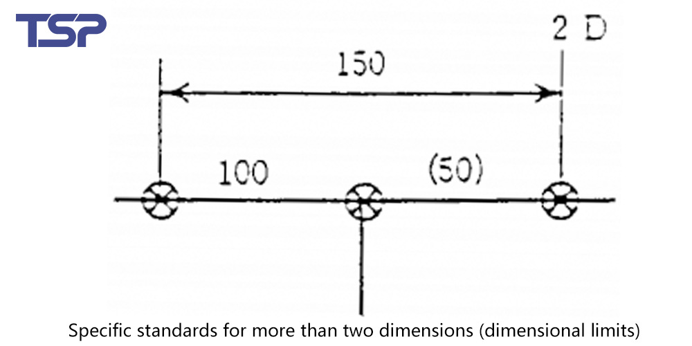
6. Dimensional Annotations and Tolerances
Standard practice involves annotating the distance between two adjacent points. If tighter tolerance is required:
Add a direct tolerance value
Do not use dimension extension lines unless strictly needed (e.g., for clip positioning)
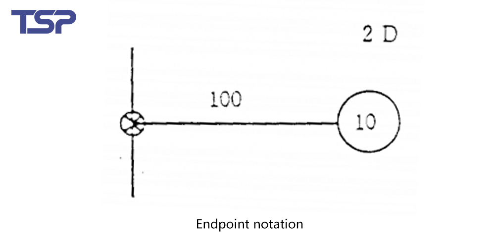
For endpoints, simply label the distance. Also, be sure to specify:
The reference surface of connectors in the technical notes.
7. Technical Requirements and Supplementary Notes
Your drawing should also include key technical specifications, such as:
Performance criteria for the harness (temperature, vibration, waterproofing, etc.)
Testing methods and requirements
Assembly instructions
Any supplemental information necessary for accurate production
These details help ensure the harness not only fits but functions correctly under all expected operating conditions.
Conclusion
Interpreting a 2D wire harness drawing correctly is crucial for engineers, assemblers, and quality control professionals. By mastering these key elements—circuit representation, connector info, routing directions, wrapping methods, fixture placement, dimensions, and tech specs—you’ll be able to understand and apply any wire harness diagram efficiently, regardless of the company or industry.
To read more: TSP Shanghai Achieves 1000KW Solar Power Milestone