In today’s rapidly evolving electronics and industrial markets, selecting the correct connector is more critical than ever. A connector may seem like a small component—but the wrong choice can compromise signal integrity, reduce reliability, increase costs, or even shut down entire systems. At TSP, we understand these challenges. With more than 26 years of experience in tooling, molding, stamping, insert-molding and full interconnect solutions, we deliver high-precision connectors and harnesses across industries like automotive, industrial, communications and smart home.
In this guide, we’ll walk you through key factors—from terminals to pins to housings—to help you make a well-informed decision. And if you’re ready to source a reliable solution, TSP stands ready to support you.
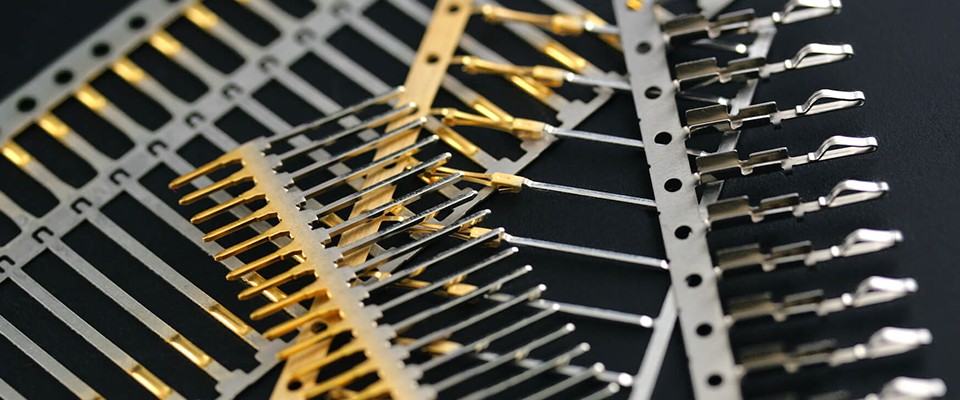
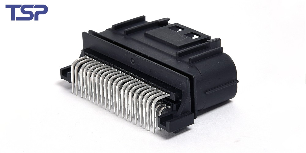
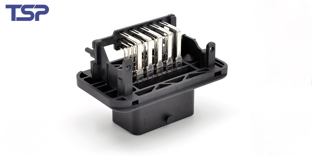
Terminals – The Foundation of a Reliable Connection
Why terminals matter
Terminals are the first element of the connector system to make contact. A high-quality terminal ensures good conductivity, low contact resistance and stable performance under vibration or environmental stress. If the terminal fails, the rest of the connector won’t perform reliably.
Key factors to consider
Material / plating: Choose materials with suitable conductivity, corrosion resistance and plating to match your application (e.g., copper alloy with gold or tin plating).
Stamping tolerance & geometry: Precision in stamping ensures consistent contact pressure and insertion/extraction performance.
Durability & mating cycles: For applications subject to repeated connections/disconnections, check the specified number of mating cycles.
Mechanical retention: Terminals should lock firmly into the housing to prevent loosening over time or under vibration.
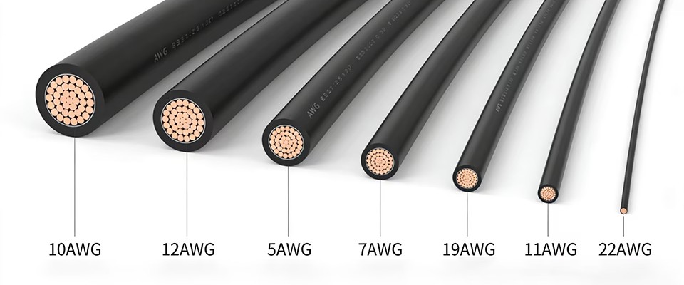
Thermal and electrical load: If the connector carries power or high currents, the terminal must handle the thermal load without degradation.
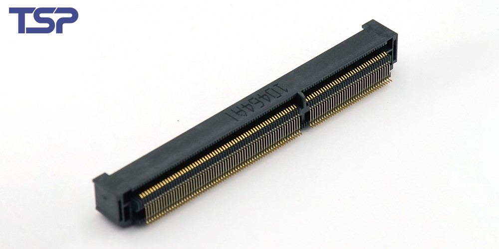
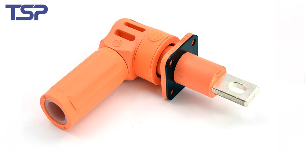
Pins and Contacts – Ensuring Signal Integrity and Power Transfer
Understanding pins vs. contacts
In many connector systems, “pin” refers to the male conductive piece, while “contact” may refer more broadly to the conductive interface (male or female). These are critical for ensuring reliable electrical performance.
Key selection criteria
Current rating & voltage rating: Ensure the contact is rated for the current and voltage of your system—over-designing wastes cost; under-designing risks failure.
Contact resistance & impedance: For signal or high-speed data applications, low resistance and consistent impedance are key to avoid loss or distortion.
Plating and finish: The contact surface finish (e.g., gold, nickel) impacts long-term reliability, corrosion resistance and contact wear.
Alignment & mating force: Proper alignment and controlled insertion force reduce wear and ensure reliable mating over multiple cycles.
Thermal expansion & environment: Especially in harsh environments (high temperature, vibration, humidity), contacts must maintain performance despite stress.
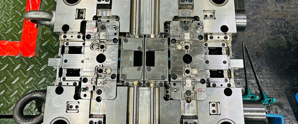
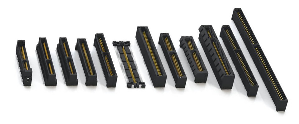
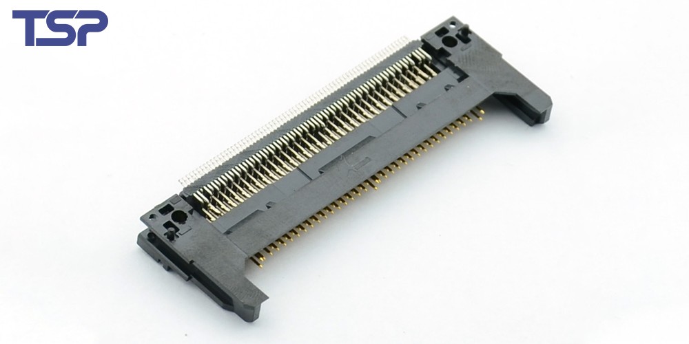
Housings and Assemblies – The “Body” That Protects and Supports
Role of the housing
The housing encloses and supports the terminals and pins, protects against environmental stresses, and ensures correct mechanical alignment and mating between connector halves. Beyond simply holding pieces together, it defines how the connector will perform in real-world conditions.
What to assess
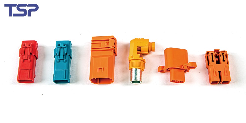
Connector type & mounting style: Board-mount, cable-mount, panel-mount, wire-to-wire, board-to-board—all have differing requirements.
Space and mechanical constraints: Evaluate the space available, orientation, insertion/extraction accessibility, and mating clearances.
Environmental rating: In industrial or automotive use, the housing may need IP ratings, vibration resistance, temperature extremes, chemical exposure etc.
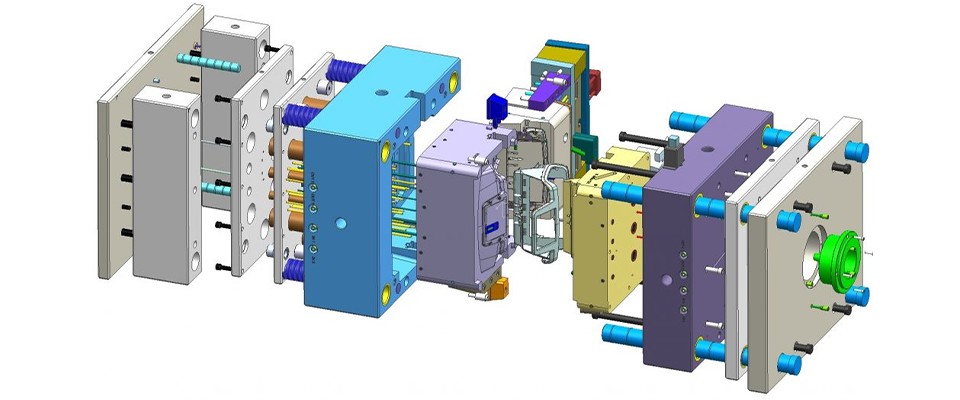
Material and manufacturing process: Materials must meet insulation, flame-retardant, mechanical and thermal performance specs. With insert-molding, over-molding or two-shot molding.
Future-proofing & modularity: Does the connector allow for future upgrades (e.g., higher data-rate contacts), expansion, or easy maintenance?
Cable/harness integration: If the connector is part of a larger harness assembly, consider how it integrates with harness design, strain relief, shielding, etc.
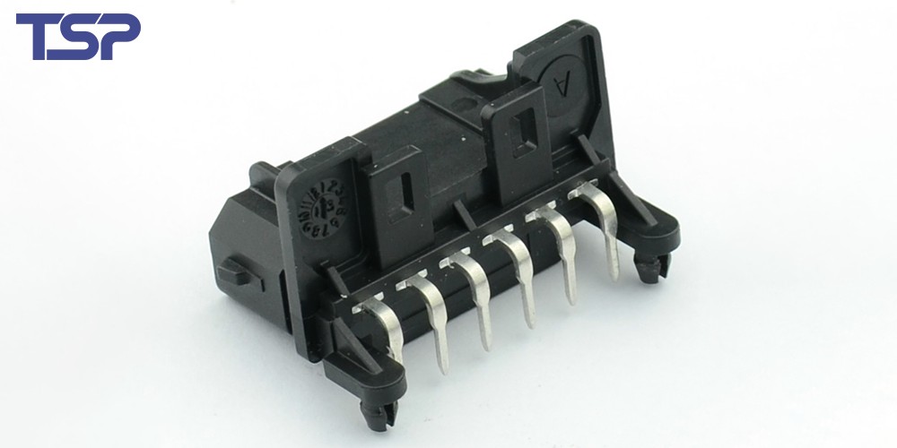
Putting It All Together – Choosing the Right Connector for Your Application
Step-by-step checklist
Define your electrical requirements: current, voltage, signal type (power vs. data), frequency.
Define your mechanical/environmental constraints: space/clearance, mating cycles, vibration/shock, temperature/humidity/chemical exposure.
Select connector family and topology: board-to-board, board-to-wire, wire-to-wire, cable assembly, etc.
Evaluate terminal and contact design: material, plating, resistance, cycle life.
Choose housing and assembly strategy: mounting style, material, manufacturing method (insert-molding, over-molding), integration with harness or board.
Consider production, supply chain and cost: Can you source at scale? Are lead-times manageable? Is the design manufacturable?
Prototype and validate: Work with engineering team to test for performance under real conditions (thermal cycling, vibration, insertion/extraction, signal integrity).
Large-scale production and quality assurance: Monitor manufacturing tolerance, batch consistency, materials traceability, testing and inspection.
Common Mistakes to Avoid
Under-specifying the connector: Choosing a connector with lower current, fewer mating cycles, or inadequate material leads to premature failure.
Ignoring the environmental conditions: High vibration, shock, humidity, chemicals or temperature extremes will degrade connectors unless specified appropriately.
Over-complicating the design: Too many special-order parts can increase cost, lead-time and supply-chain risk. A well-selected standard connector family may offer better availability.
Poor harness integration: The connector may perform well, but if the harness/cable strain relief, shielding or assembly is weak, the system can still fail.
Neglecting future scalability: Designing a connector that cannot serve higher data-rates or additional signals may force a re-design later.
Skipping prototyping / testing: Without physical validation under real-world conditions, hidden issues may emerge only after production starts.
How to Move Forward with TSP
Ready to get started? Here’s how you can engage with us:
Step 1 – Contact TSP: Reach out via sales@tsp.cn to discuss your specification, project goals and volumes.
Step 2 – Consultation & engineering support: Our engineering team will review your requirements and work with you on design, material selection and manufacturability.
Step 3 – Prototype & validation: We’ll produce prototypes, assist in testing and iterate until the solution meets your needs.
Step 4 – Production & delivery: With our global manufacturing capacity (China, Mexico, Morocco) we can scale to high volumes while maintaining quality and on-time delivery.
Step 5 – After-sales support: We continue to support you post-production with logistics, quality management and any necessary product updates.
To read more: TSP Shanghai Achieves 1000KW Solar Power Milestone