A Battery Management System (BMS) is the core intelligence of every modern lithium battery platform — from residential ESS units and large-scale energy storage stations to electric vehicles, AGVs and industrial power systems. As battery technology evolves, the wiring harness behind the BMS becomes increasingly critical. High-precision signal transmission, stable communication and reliable current pathways all depend on a well-designed BMS wiring harness.
This article analyzes the key elements of BMS wiring harness structure design, signal transmission requirements, insulation and safety considerations.
1. Why the BMS Wiring Harness Determines System Stability
The BMS wiring harness is far more than a cable bundle. It is the nerve network of any lithium battery system. Its core responsibilities include:
Collecting cell voltage signals
Transmitting temperature data
Balancing and equalization control
Carrying communication signals & CAN/RS485/SMBus
Power transmission and high-current paths
Safety feedback and fault detection
If any signal is lost, delayed or interfered with, the battery pack may experience:
✔️ Unstable SOC/SOH calculations
✔️ Overcharge / over-discharge risks
✔️ Thermal runaway risks
✔️ Degraded cycle life
✔️ System shutdown or communication interruptions
Therefore, a reliable BMS harness is essential for EV-grade reliability and ESS long-term stability.
2. Structure Design Essentials of BMS Wiring Harnesses
A high-quality BMS wiring harness must be engineered for precision and endurance. Critical design points include:
2.1 High-Density Connector Selection
The harness typically connects:
Cell voltage collection boards (VCU/DBC)
Temperature sensors
Pack-level CAN/RS485 interfaces
Current sensors / shunt / Hall sensors
2.2 Balanced Voltage Loop Architecture
For LFP (LiFePO4) and NCM systems, wiring topology must ensure:
Equal wire length for each cell sampling line
Minimized differential noise
Secure insulation spacing
Safe routing away from high-current sections
2.3 Temperature Sensing Network
A stable thermal feedback system includes:
NTC/PTC sensors
Shielded twisted pairs
Heat-resistant and flame-retardant materials
Spot welding or all-in-one integrated harness design
This ensures accurate temperature monitoring—critical for safeguarding large ESS installations.
2.4 HV and LV Separation
To avoid EMI interference:
High-voltage cables and low-voltage signal cables must be separated
ISO 21498 and EV standard routing principles are followed
Shielding may be added for CAN/RS485 communication lines
3. Signal Transmission Requirements in BMS Harnesses
Signal quality is the determining factor of BMS performance.
3.1 Voltage Sampling Accuracy
Sampling wires must ensure:
Low resistance
Minimal signal loss
Consistent voltage drop
Strong anti-interference shielding
3.2 Temperature Signal Stability
Each battery module relies on accurate NTC readings:
Incorrect readings cause false alarms
Over-sensitivity triggers unnecessary shutdowns
Low sensitivity creates thermal risk
3.3 Communication Reliability
BMS commonly uses:
CAN 2.0B
CAN FD
RS485
SMBus / I2C
UART
To guarantee reliable communication:
Shielded twisted-pair cable
Controlled impedance
EMI/EMC design principles
Robust connector locking systems
This is essential for EV, heavy equipment, and large industrial ESS.
4. Material and Manufacturing Requirements
A reliable BMS wiring harness must meet demanding mechanical and environmental conditions.
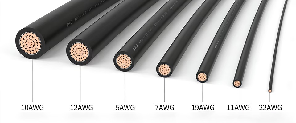
4.1 Cable Materials
XLPE insulation
TPU for abrasion resistance
High-flex silicone for EV packs
UL-certified materials for export markets
4.2 Mechanical Strength
BMS harnesses often endure:
Vibration
Temperature cycling
Chemical exposure
Installation bending
4.3 Safety Compliance
Depending on the application:
UL94-V0
ISO 19642 (Road Vehicle Wiring)
IEC 62619 (ESS Batteries)
GB/T 34013
All TSP BMS harnesses can be produced with full certification support.
5. Why Leading Battery Manufacturers Choose TSP
TSP is a global precision wiring harness and connector solution provider with manufacturing in Mexico and Morocco, serving EV, ESS energy storage, medical, and industrial customers.
✔ 6+ years OEM & ODM experience
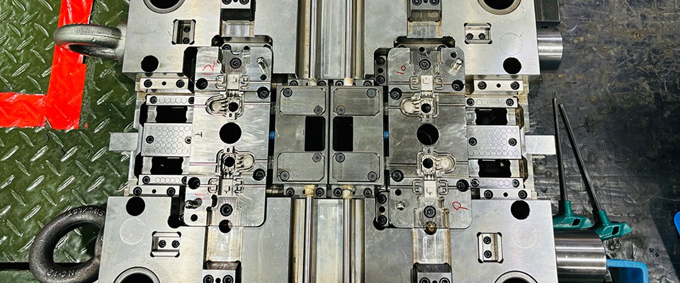
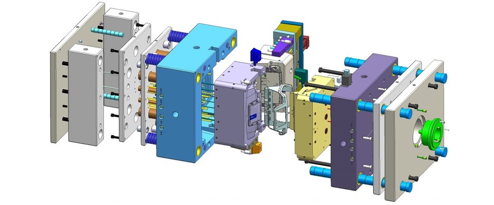
✔ Complete in-house molding and connector development
✔ Full BMS wire harness engineering capability
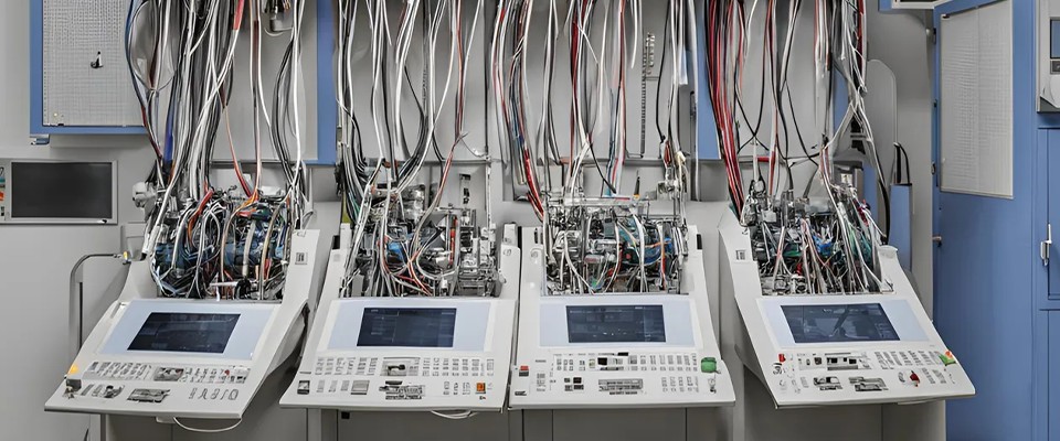
✔ Automated production for consistent quality
✔ Flexible customization from prototype to mass production
Our partners include world-class companies such as:
TE Connectivity, Sensata, Phoenix Contact, Molex, etc.
What TSP delivers:
Customized BMS wiring harness solutions
Balanced voltage sampling harness
CAN/RS485 communication harness
Pack/module temperature sensor harness
Cell monitoring board harness (CMU/VCU)
High-voltage harness with IP67/IP68 protection
We support EV battery packs, LFP energy storage cabinets, telecom backup, residential ESS, AGV/AMR batteries, UPS systems, and more.
To read more: TSP Shanghai Achieves 1000KW Solar Power Milestone