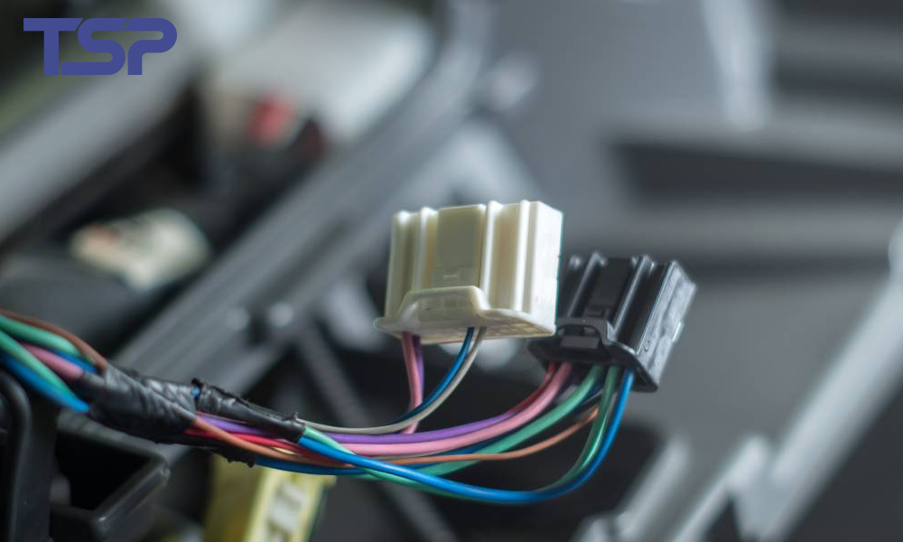
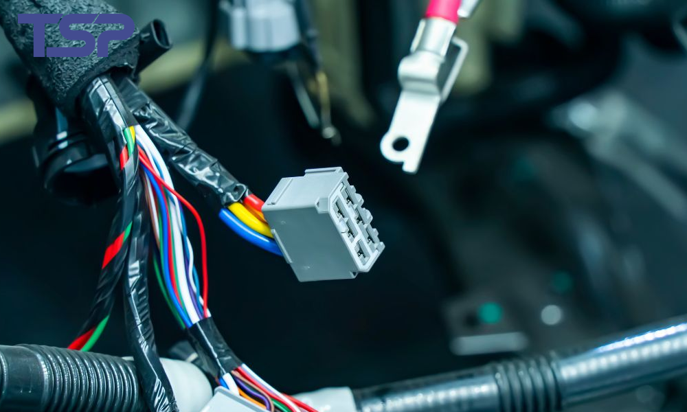
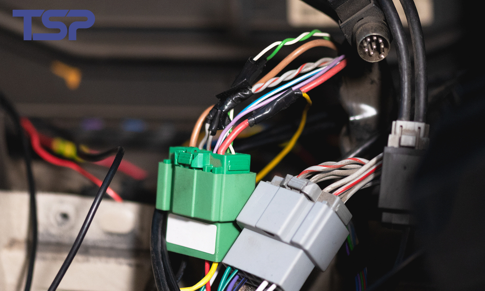
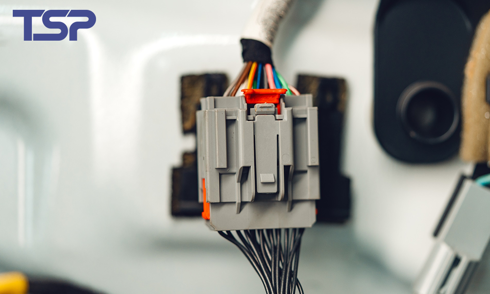
Automotive electrical connectors operate in extremely diverse environments across the vehicle. Each location—engine bay, chassis, cabin, or transmission—places different stress levels on connectors, including temperature cycling, humidity, vibration, mechanical shock, and chemical exposure.
To ensure reliability, global standards such as China’s QC/T 1067 and the U.S. USCAR-2 specification define rigorous performance requirements, including temperature classification and vibration levels.
This article consolidates and compares both standards, highlights key differences, and provides engineering insights to help you design or select connectors that meet modern automotive requirements.
1. Temperature Classification for Automotive Connectors
1.1 Overview
Although QC/T 1067 and USCAR-2 both define temperature classes, their naming methods differ. USCAR-2 uses five classes (T1–T5), while QC/T 1067 defines grades A–E. Both standards describe the expected ambient temperature range and typical installation location.
1.2 QC/T 1067 Temperature Classes
| Class | Ambient Temperature Range | Typical Installation Zone |
|---|---|---|
| A | –40°C to +85°C | Passenger compartment |
| B | –40°C to +105°C | Dry cabin (no water exposure) |
| C | –40°C to +125°C | Engine bay |
| D | –40°C to +150°C | Near heat sources, such as turbo or exhaust components |
| E | –40°C to +175°C | Extreme thermal zones; severe duty |
QC/T temperature levels reflect China’s increasing adoption of high-temperature engine technologies, especially in turbocharged gasoline powertrains.
1.3 USCAR-2 Temperature Classes
| Class | Ambient Temperature Range | Typical Application |
|---|---|---|
| T1 | –40°C to +85°C | Low-risk cabin applications; not recommended for new designs |
| T2 | –40°C to +100°C | Passenger components |
| T3 | –40°C to +125°C | Engine compartment standard class |
| T4 | –40°C to +150°C | High-temperature areas in the engine bay |
| T5 | –40°C to +175°C | Specialty applications; limited use |
USCAR-2 aligns with North American OEM requirements and is widely used by GM, Ford, and Stellantis.
1.4 Key Takeaways for Temperature Ratings
T3/C level is the most common for standard combustion engine applications.
T4/D and T5/E are essential for components near turbochargers, catalytic converters, or hybrid power electronics.
Designers should always consider derating, especially in high-current circuits where heat rise from electrical load must be added to ambient temperature.
2. Vibration Classification for Automotive Connectors
Vibration is one of the most critical reliability factors. Poor vibration performance leads to fretting corrosion, contact wear, intermittent signals, and ultimately connector failure.
Both QC/T 1067 and USCAR-2 define vibration severity levels based on installation location and expected mechanical stress.
2.1 QC/T 1067 Vibration Classes
| Class | Application Zone |
|---|---|
| V1 | Vehicle interior / dashboard |
| V2 | Body systems and cabin areas away from powertrain vibration |
| V3 | Connectors installed in environments with severe vibration |
| V4 | Install as needed in areas experiencing extreme vibration |
| V5 | On wheels |
2.2 USCAR-2 Vibration Classes
| Class | Common Name | Typical Application | Other Requirements Met |
|---|---|---|---|
| V1 | Chassis Profile | Components on sprung portions of vehicle not coupled to Engine | None |
| V2 | Engine Profile | Components coupled to Engine with no severe vibration possible | Pass on V2 ⇒ pass also for V1 |
| V3 | Severe On-Engine | Components subject to severe vibration | Pass on V3 ⇒ pass also for V1 and V2 |
| V4 | Extreme Vibration | Used as needed to correlate to extreme vibration areas | Pass on V4 ⇒ pass also for V1 and V2 and V3 |
| V5 | Unsprung Component | Wheel-mounted components | None |
2.3 QC/T 1067 vs. USCAR-2 vs. GMW-3191 Comparison
| Mounting Location | Vibration Parameters | QC/T-1067 | USCAR-2 | GMW-3191 |
|---|---|---|---|---|
| Wheel | Random Vibration (20–2000 Hz) | V5 | V5 | V3 |
| Engine | Sine Vibration (100–440 Hz) | V3 | V3 | V2 |
| Random Vibration (10–2000 Hz) | ||||
| Severe Vibration Area (ECU / EGR / Throttle Body etc.) | Sine Vibration (100–400 Hz) | V4 | V4 | V4 |
| Random Vibration (10–2000 Hz) |
This comparison shows that USCAR-2 and QC/T levels are broadly aligned, making global harmonized connector design increasingly feasible.
3. Engineering Considerations for Connector Selection
To ensure long-term reliability, engineers should evaluate:
3.1 Application Environment
Maximum ambient temperature
Temperature spikes and thermal cycling
Expected vibration energy density (PSD curves)
Fluid exposure (oil, coolant, fuel, salt spray, road debris)
3.2 Connector Structural Features
Terminal retention force
Anti-vibration terminal design (e.g., secondary locks, TPAs, CPA devices)
Seal integrity (radial seals, wire seals)
Housing material heat resistance (PA66, PBT, PPS, LCP)
3.3 System Integration
Routing strategy to minimize mechanical load
Shielding/grounding requirements for high-speed data lines
Contact plating to reduce fretting corrosion (tin vs. silver vs. gold)
To read more: TSP Shanghai Achieves 1000KW Solar Power Milestone